
From Blueprint to Print - a video #tutorial
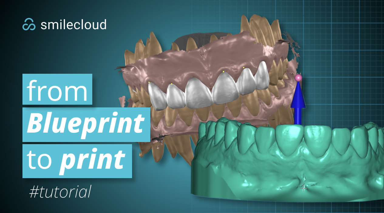
The workflow is divided into three main stages:
Exporting the project from Blueprint
Creating a single surface mesh in Meshmixer
Creating the final printable model in Exocad
Before you begin
Before starting, make sure your Blueprint project is complete and that the design you want to print has already been reviewed.
You will need:
A completed Blueprint project
The final design/mock-up
The initial scan or model surface
Meshmixer installed on your computer
Exocad Model Creator installed on your computer
Step 1: Export the project from Blueprint
Open the completed project inside Blueprint.
From the Blueprint workspace, open the Export option.
In the export window, select the objects that you need for the external workflow. For this type of workflow, you should export the final design and the model surfaces that will be prepared for printing.
Once the correct objects are selected, confirm the export and download the STL files from Blueprint.
After the download is complete, open the downloaded folder on your computer. If the export is compressed, extract the files before continuing.
Open the extracted folder and locate the STL file that will be prepared in Meshmixer.
Step 2: Open the export in Meshmixer
Open Meshmixer and import the STL exported from Blueprint.
Once the file is loaded, rotate the model and inspect the anatomy before making any changes. The imported file may contain several elements, including the initial scan, the sculpted/segmented teeth, the design teeth, gingiva, or other exported model surfaces.
At this stage, the goal is not to redesign the case. The goal is to organize the exported geometry, separate the useful elements, clean the surfaces, and prepare a file that can later be used in Exocad.
Step 3: Separate the imported objects
In Meshmixer, start by identifying the digitally sculpted initial segmented teeth.
Select these objects and use the separation tools to split it into separate shells. This is an important step because a Blueprint export can contain several disconnected pieces inside one STL object. Separating shells allows Meshmixer to treat those pieces as individual editable objects.
After separating the digitally sculpted initial segmented teeth, select the initial scan and separate it as well.
Then select the design teeth and separate them too.
The purpose of this stage is to make the different parts of the export easier to control. Once the objects are separated, you can show, hide, select, edit, or combine them more precisely. You can also export them separately from the blueprint and import them one by one in meshmixer to the same result.
Step 4: Set the target mesh
After the objects have been separated, set the digitally sculpted initial segmented teeth as the target mesh.
The target mesh acts as the reference surface. In this workflow, it is used so that the sculpting information from the digitally sculpted segmented teeth can be copied onto the initial unsegmented scan
This helps transfer the correct shape onto the scan while keeping the scan as the working base.
Step 5: Use the Attract brush to copy the sculpting
With the correct target mesh set, use the Attract brush to copy the digital sculpting from the initial segmented teeth onto the initial unsegmented scan.
Brush over the relevant areas carefully. The Attract brush pulls the active mesh toward the target mesh, helping the scan inherit the sculpted surface shape.
Work gradually and inspect the model from multiple angles while doing this. The goal is to transfer the sculpted tooth information cleanly without creating unwanted distortions or artifacts. If the scan does not have enough geometry for this operation, feel free to use the smooth brush with a small size to refine the polygon count in the affected area. This will add geometry and allow you to copy using the attract brush further.
Once the sculpting has been copied, remove the target mesh mark from the initial segmented teeth.
Step 6: Prepare the objects for Boolean operations
Next, adjust the visibility of the in-scene objects so that you are working with the initial unsegmented scan and the design teeth.
Select the initial scan and one design tooth. Use Shift to select additional objects when needed.
The design teeth meshes should then be split into separate objects per tooth. This allows each design tooth to be managed individually during the Boolean workflow. If using them combined, make sure they do not intersect each other but best results happen when limiting the number of meshes in the boolean operation
Once the correct mesh and design tooth are selected, press Accept to confirm the operation.
Step 7: Clean areas where the Boolean operation fails
If a Boolean operation fails, it usually means there is a problematic area in the mesh. This can happen because of overlapping surfaces, small artifacts, scan irregularities, thin intersections, or areas where the geometry is not clean enough for the operation to complete.
When this happens, clean the indicated area using a brush of your choice. In the video, the Add/Remove brush is used.
Use the brush to remove or adjust the problematic surface area. The goal is to simplify the geometry enough for the Boolean operation to work correctly. The goal is to simplify the geometry enough for the boolean operation to give out good results BUT without changing the gingiva on the initial scan as much as possible.
After cleaning the area, repeat or continue the Boolean operation.
Step 8: Fix the mesh after the Boolean operation
Once the Boolean operation is completed, select the resulting mesh. The edit tools/analysis tools are accessible from the sidebar menu on the left in Exocad.
Inspect the areas around the design teeth carefully. These are the areas most likely to need additional cleaning after the Boolean operation.
Look for irregular surfaces, unwanted overlaps, open areas, scan artifacts, or small pieces of geometry that should not remain in the final file.
Fix the issues around the design teeth before moving forward.
Step 9: Clean scan artifacts and unusable margins
Enter Select Mode.
Use Select Mode to mark scan artifacts and any unusable gingiva margins. These areas should be cleaned because they can interfere with the final printable model or create unnecessary complexity in the exported file.
After selecting the unwanted areas, remove them from the mesh.
Then enter Inspector Mode to identify and clean floating islands from the scan margins. Floating islands are small disconnected pieces of geometry that may not be obvious at first glance, but they can create problems later when exporting, importing, or printing.
Use Inspector Mode to clean these disconnected fragments and verify that the remaining mesh is clean and usable. Press I for a quick automatic inspection of the single surface mesh. The red dots indicate something needs to be remeshed in the highlighted area, blue - indicates a hole that needs to be closed, pink - loose islands/polygons that need to be deleted
Step 10: Export the cleaned single-surface mesh
After cleaning the model, export the result as a single surface mesh.
This is the file that will be used in another software, such as Exocad.
The goal is to leave Meshmixer with a clean STL that contains only the required geometry, without unnecessary fragments, disconnected shells, or duplicated surfaces.
Additionally you can finish the printable model here by extruding the surface edge, plane cutting the extrusion to the desired base height, hollowing the model and plane cutting once more to avoid wasted resin.
Step 11: Open Exocad Model Creator
Open Exocad and start the Model Creator workflow.
Browse for the STL file exported from Meshmixer and import it into Exocad.
Once the STL is loaded, review the model inside the Exocad workspace before continuing.
Step 12: Orient the model
Use the orientation tools to position the model correctly.
Align the model so that it sits properly on the working plane. This step is important because the model orientation affects how the base will be created and how the final file will be prepared for printing.
Inspect the model from the front, side, and occlusal views before confirming the orientation.
Step 13: Create the printable model base
In Model Creator, draw or adjust the outline for the printable model base.
Follow the shape of the arch carefully and make sure the outline supports the full design.
After the outline is defined, continue to generate the base.
Inspect the model wall and base thickness. Make sure the base is stable, continuous, and suitable for printing.
Step 14: Review the final print-ready model
Once the base has been generated, review the completed model from multiple angles.
Check that:
The design remains correctly positioned
The base supports the model properly
The wall and base thickness look appropriate
There are no visible unwanted fragments
The model is clean and ready for export
After the final inspection, export the completed print-ready model from Exocad.
Final result
At the end of this workflow, the Blueprint design has been exported, prepared in Meshmixer, cleaned into a usable single-surface mesh, and finalized in Exocad with a printable model base.
The final file can now be used for the next step in the printing workflow.